NeuroRiderVR
Background
In a recent blog post (Locomotion in VR), I detailed some of the current technology that exists for locomotion in VR. Until recently, VirZoom was the only virtual reality bike on the market. However, at CES 2019, Nordic Track announced the release of their VR bike. This is great news for VR as many of the bigger companies are starting to see the value of VR in exercise and entertainment. The target audience for both VR bikes are generally younger to middle aged adults with a focus on entertainment, exercise, and gaming.
In our academic research lab, we focus on the applications of VR to rehabilitation in an older adult population. At the time of our VR biking study in older adults, the Nordic Track VR bike did not exist. While the VirZoom bike was a possibility, we did have several concerns. Turning in VR with the VirZoom bike is achieved by leaning one’s body in the intended direction of movement. VirZoom claims that this is a more natural method of turning that minimizes motion sickness and improves user safety while riding the VR bike.
When we tried the VirZoom bike in our lab, our initial impressions were that it was a bit unnatural. While it’s possible that users would adjust to this over time, we thought the older adult population might do better on a bike with a turning mechanism that more closely resembled that of an actual bike. Furthermore, we hypothesized that requiring older adults to lean might introduce an additional safety risk, particularly in those with poor postural stability.
Objective
Our objective was to develop a custom bike that would allow for turning in VR by the same mechanism of a regular bike, rotating the handlebar clockwise or counter-clockwise. Moreover, we wanted our design to include digital control of the pedal resistance. This would allow for real-time manipulation of pedal resistance when participants were going up or down hills in a VR environment or as a means to increase a participants exertion during exercise.
Design Requirements
The primary design requirements for our custom bike were stability, comfort, and ease of access for older adults. The bike was required to accommodate adults of different heights, trunk, leg, and arm lengths, and the turning and braking mechanisms for our bike were to be similar to that of a road bike. Furthermore, the bike was to be designed such that the pedal resistance could be manipulated from the computer in real-time. Finally, the bike should be able to interface with a computer and provide speed, turning, temperature, and braking feedback.
Mechanical Design
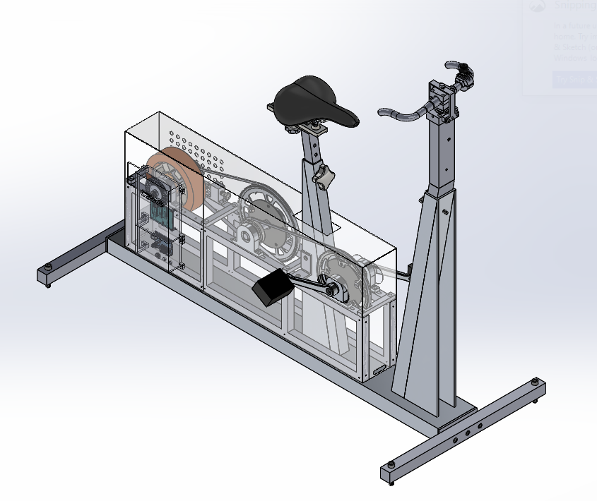
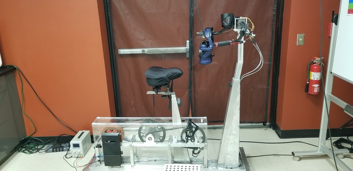
The first step in the design process was to create a model of the bike using SolidWorks, a 3D CAD software. We then had the bike fabricated at our University's (USC) machine shop. The drivetrain, handlebar, and seat post frames were welded and constructed out of aluminum to reduce weight and cost. All other components, including the leg stabilizers and gearing mechanism within the drive train were bolt-mounted for ease of assembly/disassembly. The bike was comprised of adjustable angled telescopic seat and handlebar posts. The handlebar was mounted to a ball-bearing to allow approximately 150 degrees rotation. A brass set screw was used to manually adjust the resistance to turning. The bike consisted of a double gear reduction such that the output torque was approximately 11.5% of the input torque. A freewheel sprocket was used to allow for coasting. Radially oriented electromagnets were mounted concentrically inside a flywheel to allow for varying of pedal resistance using the principles of eddy current braking.
Electrical Design
Speed Detection
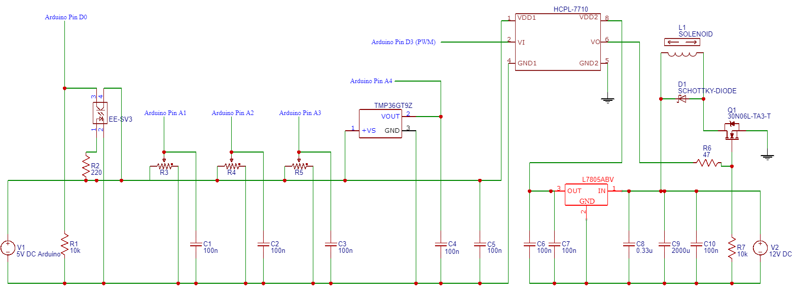
Speed detection was achieved using a custom laser-cut acrylic encoder wheel and Omron EE-SV3-D transmissive optical sensor. The optical sensor consisted of a photodiode (light emitter) and phototransistor (light detector). A standard 220 Ω resistor was connected in series between the 5V supply voltage and anode to keep the forward current within its specified current rating. The phototransistor was configured as a common collector (CC) phototransistor circuit. A 10 kΩ load resistor was added between ground and the emitter to configure the phototransistor for switch mode (), where the output was either OFF or ON based on the absence or presence of light, respectively. It should be noted that a 5 kΩ load resistor is typically adequate for switch mode and will have a faster response time to changes in light intensity compared to a 10 kΩ load resistor. The output signal from the collector was connected to a digital pin on the Arduino.
Turning and Brake Sensing
A linear, rotatory 10 kΩ potentiometer and dual-axis XY joystick module were used for turning and brake sensing, respectively. Both sensors were configured as voltage dividers, outputting a voltage between 0V and the 5V supply voltage based on the rotation of the knob or the deflection of the joystick.
Temperature Sensor
A TMP36 semi-conductor temperature sensor was used to monitor heat dissipation at the electromagnet coils. A 100 nF capacitor was added between the output pin and ground for each sensor to dampen signal fluctuations due to mechanical bounce, electrical noise, and electromagnetic interference. The output pin on each sensor was connected to a unique analog pin on the Arduino.
Pedal Resistance
Pulse width modulation (PWM) and a RFP30N06LE MOSFET transistor were used to manipulate pedal resistance. An HCPL-7710 opto-isolator was placed between the Arduino’s digital PWM signal and the MOSFET to electrically isolate the MOSFET from the Arduino. Indeed, the high PWM signal frequency (490 Hz) resulted in frequent switching of the MOSFET which caused undesirable noise during signal sampling. The PWM signal was connected to pin 2 of the opto-isolator. Arduino’s 5V power supply and ground were connected to pins 1 and 4 of the opto-isolator. 12V from an external variable power supply was regulated down to 5V via a L7805ABV linear voltage regulator and connected to pin 5 of the opto-isolator. Pin 8 of the opto-isolator was connected to ground of the external power supply. A 100 nF capacitor was connected between pins 1 and 4 and 5 and 8 of the opto-isolator in accordance with datasheet recommendations. Similarly, a 330 nF and 100 nF capacitor were connected between ground and the voltage regulator input and output pins, respectively.
The opto-isolated PWM signal at pin 6 of the opto-isolator was connected to the gate pin on the MOSFET. A 47 Ω gate resistor was placed in series with pin 6 of the opto-isolator and the MOSFET gate to limited ringing and electrical noise due to parasitic inductance. A 10 kΩ pull-down resistor was connected in series between ground and the MOSFET gate to pull the voltage down and turn the MOSFET off in the absence of a PWM input signal. The MOSFET source was connected to the source of the MOSFET. One electromagnet lead was connected to the source of the MOSFET, while the other was connected to 12V power from the external power supply. An 1N5817 Schottky diode was connected in parallel with the leads of the electromagnet to prevent flyback when current to the electromagnet is interrupted. A 2000 µF electrolytic capacitor and 100 nF capacitor were connected in parallel across 12V power and ground from the external power supply to smooth out the input voltage to the electromagnet.
Arduino Programming
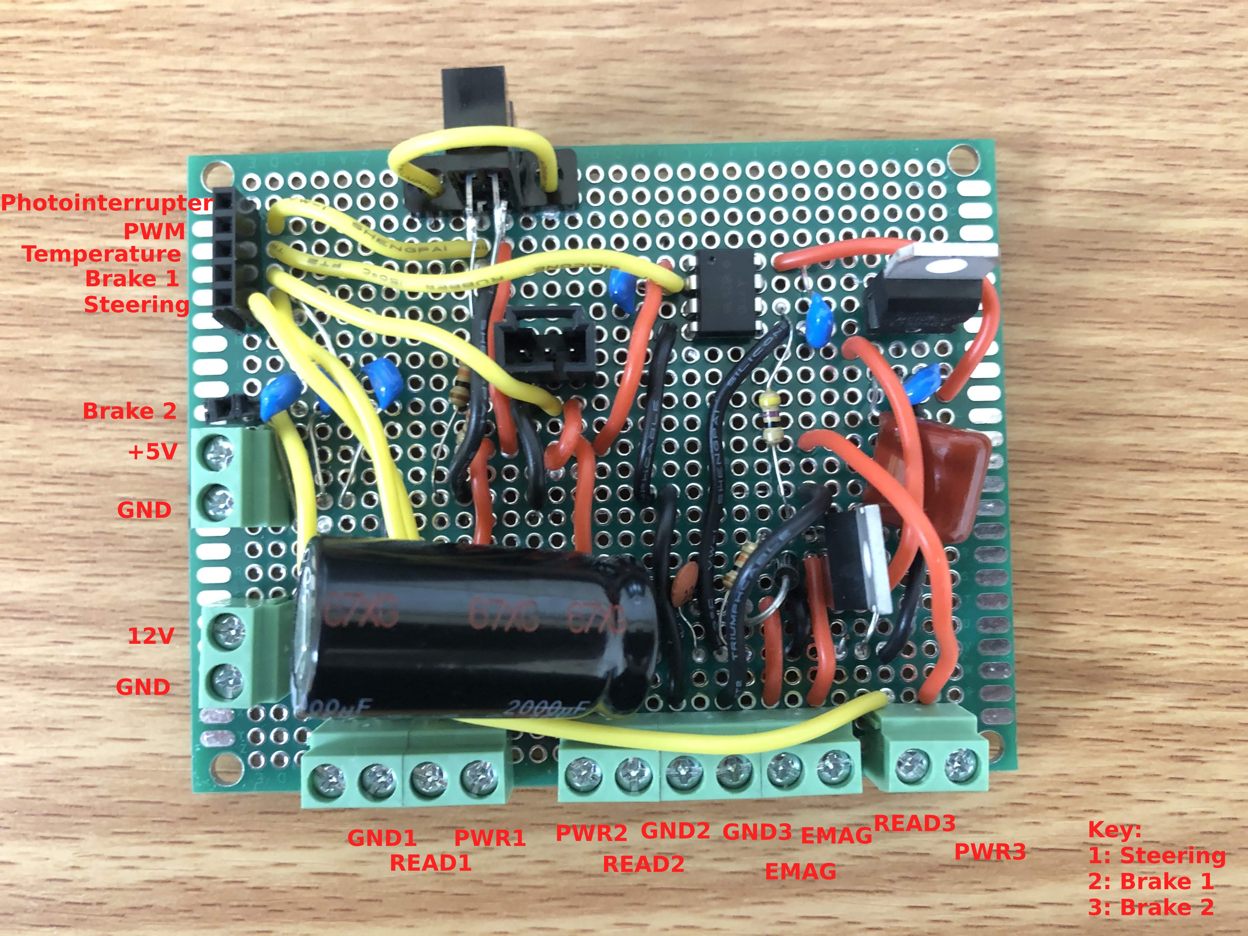
The temperature, turning, and braking sensors were connected to analog input pins, the speed sensor was connected to a digital input pin, and pedal resistance was provided by a PWM output pin on the Arduino Uno. The Arduino Uno connected to the PC via a USB A-Male to B-Male cable. A standard Arduino Uno driver was used to establish the connection as a COM port on the PC. The baud rate was set to 1,000,000 for serial port communication.
The ResponsiveAnalogRead library was used to reduce noise associated with the analog input signals for the brake, turning, and temperature sensors. All analog sensor values were updated within the main loop. For the speed sensor, an interrupt trigger was used to track when the state of the optical sensor changed. A digital pin reads HIGH(1) when the voltage signal is > 3.0V and LOW(0) when the voltage is < 3.0V on a 5V Arduino board.
When determining speed, the Arduino code is structured to count the number of times the digital interrupt is triggered over a specified sampling period of 50ms. A digital interrupt is triggered when the encoder wheel spoke enters and leaves the light path. The number of interrupts over this 50 ms period is then converted to a speed using the following formula:
Interrupt Count (counts/s) = Interrupt Count * (1 / 50 ms) * (1 / 1000s)
Speed (m/s) = (2 * pi * Flywheel Radius (m)) / (Spokes per Revolution) * (Interrupt Count)
Note: In practice, an additional fudge factor may be necessary to get the perceived pedal speed to correctly match the speed at which the user moves through the virtual environment
Encoder Wheel
The encoder wheel was mounted to the output shaft of the flywheel and centered within the gap of the optical sensor. For the encoder wheels, we laser cut 6 different variations out of acrylic. These variations included 2, 4, 8, 16, 32, 64, and 128 spokes. For each wheel, we evaluated 2 conditions: aliasing and a ceiling effect. Aliasing occurs when the encoder wheel rotates faster than the optical sensor can react to the light change or the Arduino can trigger the digital interrupt pin. With a 10K load resistor, the response time of the phototransistor is approximately 100 µs. With the Arduino, the interrupt service routine theoretically executes every .625 µS based on a clock speed of 16 MHz.
However, in practice, this is often much slower due to factors such as code overhead and often results in an interrupt frequency on the scale of milliseconds, which likely makes it the rate limiting step. The ceiling effect occurs when the resolution of the encoder wheel is too small to capture the actual pedal speed. In other words, after a certain pedal speed, the number of spokes that pass through the optical sensor gets capped over a 50 ms period. During testing, we found that the 2,4,8, and 16 spoke encoder wheels experienced the ceiling effect while the 128 spoke encoder wheel had significant aliasing at normal pedal speeds. We found the 64 spoke encoder wheel to be the best option as we found no aliasing and no ceiling effect, even at very high pedal speeds.
Acknowledgements
The bike design was a team effort with significant contributions from Roshan Ravichandran (lead mechanical design) and Delian Delev (lead electrical design). Additional design support was provided by Chintan Raja and Vincent Yang. Electromagnet guidance was provided by Andrew Bushnell. Special thanks to Don Wiggins and the USC machine shop for manufacturing the bike.